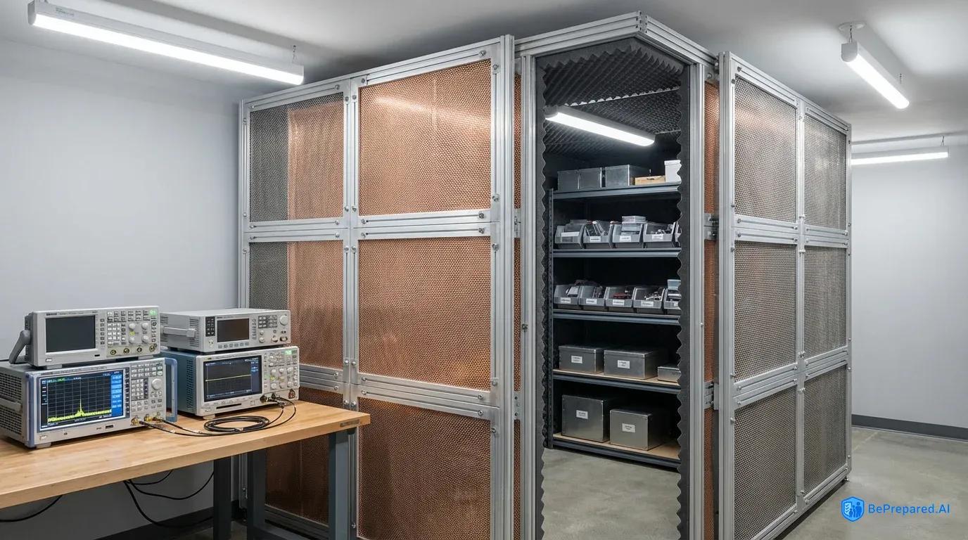
Understanding EMP Protection Fundamentals
The amateur radio operator thought he'd done everything right. His homemade Faraday cage sat in the corner of his basement—a galvanized trash can lined with cardboard, housing his backup handheld radios and spare electronics. He'd read about EMP protection online, watched several YouTube videos, and felt confident his equipment would survive a high-altitude electromagnetic pulse. What he didn't know was that his "protection" would fail catastrophically in an actual EMP event, rendering his carefully stored equipment just as useless as if he'd left it on his workbench.
This scenario plays out in thousands of homes across the country. Well-intentioned preppers invest time and money into EMP protection systems that fundamentally misunderstand the physics and engineering requirements necessary for true electromagnetic shielding. The difference between adequate and inadequate protection isn't a matter of degree—it's binary. Your equipment either survives or it doesn't. Partial protection is essentially no protection at all.
Adequate EMP protection requires achieving minimum 80dB attenuation across a broad frequency range, typically from 10 kHz to 1 GHz, as specified in military standards like MIL-STD-188-125-1 . To understand what this means in practical terms, 80dB attenuation reduces the electromagnetic field strength by a factor of 10,000. An EMP pulse that would deliver 50,000 volts per meter to unprotected electronics would be reduced to just 5 volts per meter inside a properly constructed shield. This level of reduction transforms a catastrophic threat into a manageable electrical event that most electronics can withstand without damage.
The physics behind this protection involves creating a continuous conductive enclosure that intercepts electromagnetic waves and channels them around the protected volume. This works much like how a car's metal body protects occupants during a lightning strike. However, unlike lightning protection, which primarily concerns a single, relatively slow event, EMP protection must address an incredibly fast-rising pulse with frequency components spanning several orders of magnitude. The E1 component of a nuclear EMP rises to peak field strength in approximately 2-5 nanoseconds according to electromagnetic pulse research . This rise time occurs faster than most electronic protection circuits can respond.
This brings us to perhaps the most dangerous misconception in the preparedness community: the belief that partial shielding provides partial protection. Electromagnetic shielding doesn't work on a sliding scale where better shielding equals better protection. Instead, it operates more like a dam—either it holds back the water completely, or a single breach causes catastrophic failure. A Faraday cage with a gap of just a few centimeters can allow EMP energy to couple into the protected space. This creates standing waves and potentially even concentrates the electromagnetic field in certain areas. This phenomenon, called resonance, can actually make conditions worse inside a poorly constructed shield than in free space.
The frequency spectrum of concern spans from the extremely fast-rising E1 pulse (with significant energy up to 1 GHz) through the intermediate E2 pulse (similar to lightning) down to the slower but potentially more damaging E3 pulse. The E3 component can last for minutes and induce currents in long conductors like power lines . A proper protection system must address all three components, which requires different engineering approaches. The high-frequency E1 component demands excellent shielding with minimal apertures. The low-frequency E3 component requires careful attention to grounding and the elimination of large current loops.
Many commercial products claiming "EMP protection" fail to specify their attenuation performance across the relevant frequency range. They provide no independent testing verification. A metal box with a tight-fitting lid might provide adequate shielding at low frequencies but fail completely in the GHz range where small gaps become electrically significant. At 1 GHz, the wavelength measures approximately 30 centimeters based on standard electromagnetic wave calculations. This means gaps larger than a few centimeters can act as slot antennas, efficiently coupling external fields into the protected enclosure. Professional EMP protection systems undergo rigorous testing to verify performance. The testing procedures themselves require specialized equipment and expertise that most individuals cannot access.
The E1 pulse presents the most challenging protection requirement due to its extremely short rise time and broad frequency spectrum. This component results from gamma rays from a nuclear detonation interacting with air molecules in the upper atmosphere. The interaction produces Compton electrons that generate an intense electromagnetic pulse. The E2 component resembles lightning in its characteristics but occurs simultaneously with E1, potentially overwhelming surge protection devices already stressed by the E1 pulse. The E3 component, while slower, can induce damaging currents in power transmission infrastructure and any long conductors connected to your protected equipment.
Understanding these three components helps explain why comprehensive EMP protection requires more than just a metal box. Each component attacks your electronics through different mechanisms and at different time scales. Your protection system must address all three simultaneously. A shield optimized only for high-frequency E1 protection might leave equipment vulnerable to E3-induced currents entering through power connections. Conversely, focusing solely on E3 protection through power line isolation ignores the direct coupling of E1 energy through shield imperfections.
Critical Construction and Material Mistakes
The engineering firm had been contracted to retrofit EMP protection into a critical communications facility. Their design looked impressive on paper—thick aluminum panels forming a complete enclosure around the equipment room, with all seams carefully overlapped and bolted together. During the first shielding effectiveness test, however, the results were disastrous. Instead of the specified 80dB attenuation, measurements showed barely 40dB at certain frequencies—a reduction in effectiveness of 100 times. The culprit? The engineers had used stainless steel bolts to fasten the aluminum panels. This created thousands of tiny galvanic cells that corroded over the six months between construction and testing, opening microscopic gaps in the shield.
Material selection for EMP protection extends far beyond simply choosing "metal" for your enclosure. The specific metals used, their thickness, their surface preparation, and most critically, how different metals interact with each other, determine whether your protection system will function as designed or fail when you need it most. Galvanic corrosion between dissimilar metals represents one of the most insidious failure modes in EMP protection systems because it occurs invisibly over time, gradually degrading protection until a system that initially met specifications becomes essentially worthless .
Galvanic corrosion occurs when two dissimilar metals are in electrical contact in the presence of an electrolyte—which can be as simple as humid air or condensation. The more electrochemically active metal (the anode) corrodes preferentially, often at an accelerated rate compared to normal atmospheric corrosion. In the context of EMP shielding, this corrosion typically occurs at seams and fastener locations, precisely where you need the most intimate electrical contact to maintain shielding integrity. A copper mesh shield fastened with steel screws will develop corrosion products at every fastener location. This increases contact resistance and creates gaps in the shield as the corrosion products expand and push the materials apart.
The galvanic series ranks metals by their electrochemical potential, from anodic (most active) to cathodic (least active). Magnesium and zinc occupy the anodic end, while gold and platinum sit at the cathodic extreme. Aluminum, commonly used for shielding due to its excellent conductivity-to-weight ratio and ease of fabrication, falls in the middle of the series. When aluminum contacts more noble metals like copper, stainless steel, or even regular carbon steel in some environments, the aluminum corrodes. This poses a particular challenge because copper and aluminum are both excellent conductors frequently specified for shielding applications, yet they cannot be directly joined without special precautions.
Professional EMP protection installations address galvanic corrosion through several strategies. The most straightforward approach uses a single metal throughout the construction—all aluminum or all steel, including fasteners, panels, and conductive gaskets. When different metals must be used, engineers specify special bi-metallic transition washers or plates that incorporate a barrier layer to prevent direct contact. Another approach applies conductive coatings that serve as both a corrosion barrier and an electrical bridge. These coatings require careful selection to ensure they don't introduce their own galvanic issues or degrade over time.
Beyond galvanic concerns, the fundamental choice of shielding material involves trade-offs between conductivity, magnetic permeability, weight, cost, and fabrication complexity. Copper provides excellent conductivity and shields effectively against electric fields, but offers minimal protection against magnetic fields at lower frequencies. Steel, particularly high-permeability alloys like mu-metal, excels at magnetic shielding but weighs significantly more than aluminum. Steel requires more sophisticated fabrication techniques to maintain shielding integrity at seams. Aluminum represents a practical middle ground—good conductivity, reasonable weight, easy to work with, and relatively inexpensive—which explains its prevalence in commercial shielding applications.
Material thickness affects shielding performance, though the relationship is not linear. For most practical EMP protection scenarios, relatively thin materials provide adequate shielding. Common industry practice suggests that thin copper or aluminum sheets offer excellent attenuation at most frequencies of concern. Thicker materials provide diminishing returns in terms of shielding effectiveness, though they may offer practical advantages in terms of structural rigidity and durability. The exception involves very low-frequency magnetic fields, where skin depth becomes relevant and thicker high-permeability materials provide better attenuation.
The skin depth phenomenon describes how electromagnetic fields penetrate conductive materials. At higher frequencies, fields concentrate near the surface of conductors, making additional thickness beyond several skin depths irrelevant for shielding purposes. At lower frequencies, fields penetrate more deeply, requiring thicker materials for equivalent attenuation. This frequency-dependent behavior means that a single material thickness cannot optimize performance across the entire EMP spectrum. Practical designs choose thickness based on the most challenging frequency range and accept over-design at other frequencies.
Improper seam construction creates EMP leakage paths that can completely negate otherwise excellent shielding, yet seams represent the most challenging aspect of shield construction . A simple butt joint between two metal panels, even if welded, may not provide adequate RF continuity. Welding changes the metal's properties in the heat-affected zone, potentially creating high-resistance paths. Professional installations typically specify overlapping seams with continuous conductive bonding along the entire length. This is achieved through welding, brazing, or specialized conductive gaskets compressed by closely-spaced fasteners.
The "pigtail" grounding method, where a wire is attached to a panel with a ring terminal and screw, represents another common construction error. At high frequencies, even a few centimeters of wire exhibits significant inductance, creating a high-impedance path that defeats the grounding attempt. Proper high-frequency grounding requires wide, flat conductors with the shortest possible path length. Better yet, continuous contact across the entire seam provides optimal performance. The rule of thumb in shielding engineering states that fasteners along a seam should be spaced no farther apart than one-twentieth of a wavelength at the highest frequency of concern. At 1 GHz, based on electromagnetic wavelength calculations, this translates to fastener spacing of approximately 1.5 centimeters.
Door and access panel construction presents particularly difficult challenges. These features must provide both physical access and electromagnetic continuity. A door that opens creates a potential slot antenna at its perimeter. The door's edges must make intimate electrical contact with the frame around the entire perimeter when closed. Professional shielded enclosures use specialized RF gaskets—typically conductive elastomers, wire mesh, or fingerstock—compressed between the door and frame. These gaskets must maintain their conductivity and resilience through thousands of open/close cycles while resisting environmental degradation.
The amateur builder attempting to retrofit EMP protection into an existing structure faces additional complications. Penetrations for power, data, ventilation, and plumbing create potential shield breaches that require careful treatment. Each penetration needs specialized filters or waveguide-below-cutoff sections to maintain shielding integrity. A simple pipe passing through a shielded wall acts as an antenna. It efficiently couples external electromagnetic energy into the protected space unless properly treated with circumferential bonding and potentially RF chokes or filters.
Conductive gasket selection involves balancing competing requirements. The gasket must provide low electrical resistance across its entire length while maintaining sufficient mechanical compliance to accommodate surface irregularities and manufacturing tolerances. It must resist compression set—the tendency of compressed materials to lose their springiness over time. Environmental resistance matters too. Gaskets exposed to temperature extremes, UV radiation, or chemical contaminants must maintain their properties despite these stresses. Different gasket technologies excel in different applications, and selecting the wrong gasket type for your specific requirements can lead to premature failure.
Wire mesh gaskets provide excellent shielding effectiveness and good environmental resistance but require significant compression force to achieve low contact resistance. This compression force can deform lightweight door frames or require heavy-duty latching mechanisms. Conductive elastomer gaskets require less compression force but may degrade faster in harsh environments. Fingerstock gaskets—spring metal contacts that wipe against the mating surface—provide consistent performance across a wide range of compression forces but cost more than other gasket types. Understanding these trade-offs helps you select appropriate gasket technology for your specific application.
- Faraday Cage Ventilation Specs
- Double-shielded intake/exhaust system with 40dB+ attenuation, mesh size <1mm, airflow rate 100-200 CFM
- Thermal Management System
- Redundant temperature sensors, -20°C to +50°C operating range, automated cooling triggers at 30°C
Environmental Control and Maintenance Failures
The telecommunications company discovered the problem during a routine inspection of their EMP-protected equipment vault. Water droplets clung to the ceiling, and closer examination revealed corrosion on several equipment chassis and a distinct musty odor. The vault's environmental controls had failed six months earlier. Without proper ventilation, temperature differentials between the cool concrete walls and warmer interior air had created a condensation factory. Improper ventilation leads to condensation damage that can destroy electronics just as effectively as an EMP—and far more certainly, since condensation happens continuously while EMP remains a potential threat .
Environmental control in EMP-protected spaces requires balancing competing demands: maintaining shielding integrity while providing adequate air exchange, controlling temperature and humidity, and preventing condensation. Each of these challenges requires specific solutions implemented in a particular sequence to ensure long-term protection of both the shield and the stored equipment.
Step 1: Assess Ventilation Requirements
Begin by calculating the minimum air exchange rate needed for your protected space. Even sealed enclosures containing no active electronics require some air exchange to prevent humidity buildup from temperature cycling. For every 10°C temperature swing, relative humidity can change by approximately 50%. This means a space that's comfortable at 20°C and 50% RH will reach 100% RH (condensation point) if temperature drops to 10°C without air exchange. Calculate your space's volume and determine the expected temperature range based on its location. Basement installations typically see smaller temperature swings than above-ground locations, but they often start with higher baseline humidity.
The calculation should account for both the volume of air that needs exchange and the rate at which moisture enters the space. Moisture sources include air leakage from surrounding spaces, moisture migration through walls and floors, and moisture released from stored materials. Concrete walls, common in basement installations, can release significant moisture as they cure or as groundwater migrates through them. Wood shelving and cardboard boxes absorb and release moisture as humidity changes, acting as moisture buffers that can either help or hinder humidity control depending on the situation.
Step 2: Design Waveguide Ventilation Ports
Ventilation openings in EMP shields cannot simply be holes—they must incorporate waveguide-below-cutoff sections that allow air passage while blocking electromagnetic energy. A waveguide acts as a high-pass filter, blocking frequencies below its cutoff frequency while allowing higher frequencies to pass. By making the waveguide's cross-sectional dimensions small relative to the wavelength of concern, you create a structure that blocks EMP energy while passing air. For protection against frequencies down to 10 kHz (wavelength of 30 kilometers), waveguides with circular openings of 2-3 centimeters diameter and lengths of at least 10 diameters provide adequate attenuation. Multiple small waveguides provide better airflow than a single large opening while maintaining shielding effectiveness.
The waveguide design must consider both electromagnetic and airflow performance. Longer, narrower waveguides provide better electromagnetic attenuation but restrict airflow and increase pressure drop. Shorter, wider waveguides allow better airflow but may compromise shielding at lower frequencies. The optimal design depends on your specific requirements—a storage facility for inactive equipment can tolerate restricted airflow, while a shelter for occupied use requires substantial ventilation despite the electromagnetic challenges this creates.
Waveguide construction requires attention to detail. The interior surfaces must be conductive and electrically continuous with the shield. Seams or joints in the waveguide can create discontinuities that allow electromagnetic leakage. For circular waveguides, seamless metal tubing provides the best performance. For rectangular waveguides, welded construction ensures continuity. The waveguide must bond to the shield with the same care given to any other shield penetration—continuous electrical contact around the entire perimeter, with no gaps or high-resistance joints.
Step 3: Implement Humidity Monitoring and Control
Install calibrated hygrometers inside the protected space to continuously monitor relative humidity. Digital hygrometers with data logging capability allow you to track trends and identify problems before they cause damage. Relative humidity control typically targets the 30-50% range for electronics storage. This range stays low enough to prevent corrosion and biological growth, but high enough to avoid static electricity problems and material degradation from excessive dryness. For passive humidity control in smaller enclosures, desiccant materials like silica gel or molecular sieves absorb moisture, but these require regular regeneration or replacement. Desiccant quantity calculations should account for both enclosure volume and expected humidity load, with typical applications requiring substantial desiccant capacity per cubic meter of enclosed volume.
Desiccant selection involves understanding the different types and their properties. Silica gel, the most common desiccant, comes in indicating and non-indicating varieties. Indicating silica gel contains a color-changing compound that shows when the desiccant has absorbed its capacity of moisture—typically changing from blue or orange to pink or green. This visual indication simplifies maintenance by showing when regeneration or replacement is needed. Non-indicating silica gel costs less but requires weighing to determine saturation level.
Molecular sieves, synthetic zeolites with precisely controlled pore sizes, can achieve lower humidity levels than silica gel and work effectively at higher temperatures. However, they cost more and can release absorbed moisture suddenly if temperature rises significantly. Calcium chloride desiccants absorb large quantities of moisture but liquefy as they do so, creating a corrosive brine that can damage electronics if the container leaks. For most EMP protection applications, indicating silica gel provides the best balance of performance, cost, and safety.
Step 4: Address Temperature Regulation
Temperature fluctuations can degrade protection materials through repeated thermal expansion and contraction cycles that loosen fasteners, crack solder joints, and degrade gasket compression . Thermal cycling also drives moisture movement, as water vapor migrates from warmer to cooler areas where it condenses. Locate your EMP-protected storage in the most thermally stable area available—interior basement locations typically offer the best stability. If temperature control is necessary, ensure any HVAC equipment serving the space includes proper EMP filtering on power lines. Supply and return ducts must incorporate waveguide sections where they penetrate the shield. Passive temperature stability through thermal mass often provides a more reliable solution than active climate control, which introduces additional penetrations and potential failure points.
Thermal mass stabilization works by surrounding your protected space with materials that resist temperature change. Concrete walls provide excellent thermal mass. Earth berming—surrounding the structure with soil—provides even better thermal stability. Water, with its high specific heat capacity, provides exceptional thermal mass per unit volume, though using water for thermal stabilization introduces moisture management challenges. The goal is to create an environment where temperature changes occur slowly enough that your ventilation system can maintain equilibrium without large temperature swings inside the protected space.
Different materials expand and contract at different rates as temperature changes. This differential expansion creates mechanical stress at joints between dissimilar materials. Aluminum expands roughly twice as much as steel for a given temperature change. A joint between aluminum and steel components will experience stress with every temperature cycle. Over hundreds or thousands of cycles, this stress can loosen fasteners, crack welds, or degrade gasket compression. Designing for thermal stability minimizes these cycles and extends the service life of your protection system.
Step 5: Establish Condensation Prevention Protocols
Condensation occurs on surfaces that drop below the dew point temperature of the surrounding air. In EMP-protected spaces, condensation typically forms on exterior walls that contact cooler earth or outside air, and on metal shield surfaces that conduct heat away from the interior. Prevent condensation through a combination of insulation and air circulation. Install closed-cell foam insulation on interior surfaces of exterior walls to raise their temperature above the dew point. Ensure air circulation within the protected space reaches all surfaces—dead air pockets against walls create prime condensation zones. Small battery-powered fans can maintain air circulation without requiring penetrations for power lines, though their batteries need regular replacement as part of your maintenance schedule.
Closed-cell foam insulation provides both thermal resistance and a vapor barrier, preventing moisture migration through walls. Open-cell foam provides thermal resistance but allows moisture migration, making it less suitable for condensation prevention. The insulation thickness required depends on the temperature differential between inside and outside the protected space and the desired interior surface temperature. Thermal modeling or empirical testing helps determine adequate insulation thickness for your specific conditions.
Air circulation patterns matter as much as air movement quantity. Fans should direct air across surfaces prone to condensation, preventing the stagnant boundary layer where condensation forms. Position fans to create circulation patterns that reach corners and other areas where natural convection might not provide adequate air movement. Monitor surface temperatures in suspected problem areas using infrared thermometers or thermal imaging cameras to verify that your circulation strategy keeps all surfaces above the dew point.
Step 6: Develop Inspection and Maintenance Schedule
Environmental control failures typically develop gradually, giving you opportunities to detect and correct problems before they cause damage—if you're looking for them. Establish a monthly inspection routine that includes checking hygrometer readings, visually inspecting for condensation or corrosion, verifying desiccant condition (color-indicating silica gel simplifies this check), and testing any active environmental control systems. Every six months, conduct a more thorough inspection that includes checking seam integrity, testing door gasket compression, and verifying that fasteners remain tight. Temperature cycling causes differential expansion between dissimilar materials, which can loosen fasteners over time. Document all inspections and any corrective actions taken—this documentation helps identify trends and proves valuable if you need to troubleshoot recurring problems.
The inspection checklist should be comprehensive and specific. Rather than noting "check for corrosion," specify exactly where to look and what constitutes acceptable versus unacceptable corrosion. Include photographs of acceptable conditions to provide a reference standard. Define specific criteria for each inspection item—for example, "all fasteners should require at least one-quarter turn to tighten" rather than "check that fasteners are tight." This specificity ensures consistent inspections regardless of who performs them and creates objective records that support trend analysis.
Maintenance scheduling should account for both calendar time and environmental exposure. A protection system in a stable, climate-controlled environment might need only annual detailed inspections. The same system in a coastal environment with salt air exposure might require monthly detailed inspections to catch corrosion before it compromises shielding. High-vibration environments accelerate fastener loosening. Temperature-cycling environments stress gaskets and joints. Tailor your maintenance schedule to your specific environmental challenges rather than following a generic schedule that might not match your conditions.
The environmental control system should function as an integrated whole rather than isolated components. Ventilation affects both temperature and humidity. Temperature changes drive humidity fluctuations. Humidity impacts corrosion rates on shield materials. Each element influences the others, and changes to one aspect require reassessing the entire system. A protection system that works flawlessly in a dry climate may fail catastrophically when moved to a humid coastal environment without environmental control modifications.
Internal Storage Configuration Errors
Two identical Faraday cages sat side by side in a research laboratory, both constructed to the same specifications with verified 80dB attenuation. Researchers placed identical smartphones in each cage and subjected both to simulated EMP pulses. The phone in the first cage survived repeated exposures without damage. The phone in the second cage failed on the first pulse. The difference? The second cage had the phone resting against its metal wall, while the first suspended the phone in the center using non-conductive foam supports. This simple configuration difference transformed a working protection system into an expensive paperweight.
The internal configuration of EMP-protected storage receives far less attention than shield construction, yet it determines whether your equipment actually survives even when the shield performs as designed. Understanding these requirements means comparing different approaches to internal storage and recognizing how seemingly minor details create major performance differences.
Conductive versus non-conductive foam represents the first critical decision. Non-conductive foam—the type used for shipping electronics—keeps items from physically contacting the shield walls but provides no electromagnetic benefits. Items suspended in non-conductive foam can still experience induced currents and voltages from electromagnetic fields that penetrate any shield imperfections or enter through necessary openings. Conductive foam, typically polyurethane or polyethylene impregnated with carbon or metal particles, serves a different function entirely. Conductive foam must contact all surfaces to prevent resonance that can develop inside the shielded enclosure .
When electromagnetic energy enters a shielded enclosure through imperfections or necessary penetrations, it doesn't simply dissipate—it reflects off the interior walls, creating standing wave patterns. At certain frequencies determined by the enclosure's dimensions, these standing waves can create field strengths inside the shield that exceed the external field strength. This phenomenon, called resonance, occurs at specific frequencies where the enclosure dimensions equal multiples of half-wavelengths. A shield that provides excellent attenuation at most frequencies can actually amplify fields at its resonant frequencies. Conductive foam lining the interior surfaces absorbs electromagnetic energy rather than reflecting it, damping resonances and preventing field concentration.
The application technique for conductive foam matters as much as the material itself. Foam must make continuous contact with the shield walls—gaps and air pockets defeat its purpose. Cut foam pieces slightly oversized and compress them into place, ensuring intimate contact. Pay special attention to corners and edges where gaps commonly occur. For equipment storage, create custom cutouts in the foam that hold items securely while maintaining foam contact with the shield. The foam should completely surround stored items on all sides, creating a continuous absorptive medium throughout the protected volume.
Conductive foam comes in different grades with varying conductivity levels. Higher conductivity foam provides better absorption but typically costs more and may be less durable. The foam's conductivity must be high enough to absorb electromagnetic energy effectively but not so high that it creates short-circuit paths between stored equipment and the shield. Foam manufacturers specify surface resistivity—the resistance measured across the foam surface—which should typically fall in the range of 10^4 to 10^6 ohms per square for EMP protection applications.
Minimum spacing requirements between stored items prevent electromagnetic coupling between devices. When multiple electronic items are stored in close proximity, an EMP pulse can induce currents in one device that then couple to adjacent devices through capacitive or inductive mechanisms. Maintaining adequate separation between stored items, with conductive foam filling the space between them, provides isolation for most applications. Larger or more sensitive items may require greater separation—the conservative approach treats each stored item as if it might become an electromagnetic radiator and provides enough isolation to prevent that radiation from affecting other stored equipment.
The spacing requirement derives from near-field electromagnetic coupling behavior. In the near field (distances less than one wavelength), electromagnetic coupling between objects occurs primarily through capacitive and inductive mechanisms rather than radiation. Two metal objects separated by a small distance form a capacitor, and time-varying voltages on one object couple to the other through this capacitance. Similarly, current-carrying conductors create magnetic fields that induce currents in nearby conductors. Adequate spacing reduces these coupling mechanisms to negligible levels.
Grounding within the storage configuration presents counterintuitive challenges compared to conventional electrical grounding. In normal electrical systems, you ground equipment to provide a low-impedance path for fault currents and to establish a common reference potential. Inside an EMP-protected enclosure, the shield itself serves as the reference ground, and stored equipment should generally remain isolated from this ground. Grounding stored equipment to the shield can create current paths that couple external electromagnetic energy into the equipment—exactly what you're trying to prevent.
The exception to this isolation rule involves equipment with large metal chassis or cases. These structures can develop significant voltage potentials relative to the shield if left floating, potentially causing damage when equipment is removed from the shield and the potential equalizes. For such equipment, a high-impedance connection to the shield—typically through a high-value resistor (1 megohm or greater)—bleeds off accumulated charge slowly while presenting high impedance to fast EMP pulses. This approach balances the competing requirements of charge dissipation and electromagnetic isolation.
Battery-powered equipment introduces additional configuration considerations. Batteries store energy chemically, making them inherently EMP-resistant, but the circuitry they connect to remains vulnerable. For maximum protection, store battery-powered devices with batteries removed and stored separately. This configuration eliminates any possible current path through the device during an EMP event. If batteries must remain installed—for example, in devices where battery removal would lose stored settings—ensure the device is completely powered off, not just in standby mode. Many modern electronics maintain active circuitry even when "off," and this circuitry can provide a path for EMP-induced currents.
Devices with external antennas or long cables present special challenges. An antenna is literally designed to couple electromagnetic energy into a device—the opposite of what you want during an EMP event. Remove all external antennas before storage, and if possible, cap antenna connectors with 50-ohm terminations to prevent the connector itself from acting as a stub antenna. Long cables act as antennas even if not designed as such, and they can carry EMP-induced currents deep into equipment. Store cables separately from equipment, or if cables must remain connected, coil them tightly and secure the coils with conductive tape to minimize their effective antenna length.
The coiling technique for cables requires understanding transmission line behavior. A loosely coiled cable maintains its characteristic impedance and can efficiently conduct EMP-induced currents. A tightly coiled cable with turns in intimate contact creates a different electromagnetic structure with higher inductance and lower efficiency as an antenna. Securing the coil with conductive tape provides additional damping by creating eddy current paths that dissipate electromagnetic energy. The coil diameter should be as small as practical—larger diameter coils enclose more magnetic flux and couple more strongly to magnetic fields.
The comparison between proper and improper storage configuration becomes stark when examining failure mechanisms. Properly configured storage—conductive foam contacting all surfaces, adequate spacing between items, appropriate grounding strategy, antennas and cables addressed—creates a benign electromagnetic environment inside the shield. Even residual fields from shield imperfections cause minimal stress on stored equipment. Improperly configured storage—items touching shield walls, equipment crowded together, improper grounding, antennas attached—can transform minor shield imperfections into catastrophic failure modes. Equipment experiences field strengths approaching or even exceeding what it would experience outside the shield entirely.
Testing and Verification Oversights
The prepper had invested thousands of dollars in a commercial EMP protection container, a welded steel box with impressive specifications and professional-looking construction. He'd carefully loaded it with backup communications equipment, spare electronics, and critical replacement parts. What he'd never done was test it. Five years later, when he finally arranged for professional shielding effectiveness testing, the results showed less than 30dB attenuation at key frequencies—barely one-tenth the advertised performance. Subsequent investigation revealed that shipping damage had deformed the door, preventing proper gasket compression. The container had been compromised from the day it arrived, and he'd never known because he'd never tested it.
Regular testing is required to maintain protection levels because shielding effectiveness degrades over time through mechanisms both obvious and subtle . Obvious degradation includes physical damage, corrosion, and fastener loosening. Subtle degradation involves gasket compression set, conductive coating wear, and environmental contamination. Without periodic verification, you cannot know whether your protection system functions as designed or has degraded to uselessness.
Professional shielding effectiveness testing requires specialized equipment—network analyzers, calibrated antennas, signal generators, and spectrum analyzers—with costs ranging from tens of thousands to hundreds of thousands of dollars. This equipment measures the electromagnetic field strength outside and inside the shield across the frequency range of concern, calculating attenuation at each frequency. The testing procedure follows standards like IEEE 299 or MIL-STD-188-125, which specify antenna positions, measurement frequencies, and acceptance criteria. For most individuals and even small organizations, conducting this level of testing in-house is impractical.
However, the impossibility of conducting full professional testing doesn't eliminate the need for verification. Several practical approaches provide meaningful confidence in your protection system's performance without requiring sophisticated equipment. The most accessible method uses a cell phone as a test device. Cell phones operate in the 700-2100 MHz range—frequencies where shield performance often degrades first due to small gaps and imperfect seams. Place an active cell phone inside your shielded enclosure and seal it. Call the phone from another device. If the call connects, your shield has significant leakage in the cellular frequency bands, indicating probable problems across the frequency spectrum. If the call fails to connect, your shield provides at least enough attenuation to block cell signals—typically 80-100dB, which suggests adequate performance.
The cell phone test provides a quick go/no-go assessment but offers limited diagnostic information. A more sophisticated approach uses an AM/FM radio and a portable transmitter. Place a battery-powered AM/FM radio inside the shield tuned to a weak station, then seal the shield. If the station remains audible, the shield has significant leakage in the AM (520-1710 kHz) or FM (88-108 MHz) bands. For a more controlled test, use a low-power FM transmitter (legally limited to approximately 200 feet range) positioned near the shield. Place a radio inside the shield tuned to the transmitter's frequency. Seal the shield and verify that the transmitted signal cannot be received inside—if it can, you've identified a shielding deficiency.
These simple tests don't replace professional verification but they catch gross failures that would render your protection system useless. A shield that blocks cell phone signals and FM radio transmissions demonstrates basic shielding integrity across a significant frequency range. A shield that fails these simple tests certainly won't provide adequate EMP protection and needs immediate attention. The tests cost nothing beyond equipment you likely already own and can be performed as frequently as desired without specialized training.
Specific verification procedures required for certification in critical infrastructure applications involve much more rigorous testing protocols . These procedures test not just the shield itself but the entire protection system including filters, grounding, and internal configuration. Testing occurs at multiple frequencies spanning the threat spectrum, with measurements taken at numerous locations inside the protected volume to identify resonances and field concentrations. The testing generates detailed reports documenting performance at each frequency and location, creating a baseline for comparison during subsequent periodic testing.
For individuals and organizations unable to access professional testing services, developing a comprehensive inspection protocol provides an alternative verification approach. This protocol should address every element that contributes to shielding effectiveness, creating a systematic checklist that leaves nothing to chance. Begin with visual inspection of all accessible seams, looking for gaps, corrosion, or damage. Check that all fasteners remain tight—use a torque wrench to verify fastener torque matches specifications if available. Inspect door gaskets for compression set, tears, or contamination. Check that gaskets make continuous contact around the entire door perimeter when closed, with no visible gaps.
Examine all penetrations for proper treatment. Power line filters should show no physical damage and their ground connections should remain intact and tight. Waveguide ventilation sections should be clear of obstructions and show no corrosion or damage. Any cables or pipes passing through the shield should maintain their circumferential bonding or other specified treatment. Document all findings photographically, creating a visual record that enables comparison during future inspections to identify developing problems.
Environmental monitoring data provides indirect verification of shield integrity. Unexpected temperature or humidity changes can indicate air leakage through shield breaches. Sudden humidity increases might point to gasket failure allowing outside air infiltration. Temperature instability could indicate penetration problems allowing thermal transfer. While these indicators don't directly measure electromagnetic shielding effectiveness, they reveal physical integrity problems that often correlate with shielding degradation.
Testing frequency depends on the installation's criticality and environmental exposure. Minimum annual testing catches most degradation mechanisms before they compromise protection, but more frequent testing—quarterly or even monthly—makes sense for critical applications or harsh environments. Coastal installations face accelerated corrosion and should be tested more frequently than climate-controlled interior locations. Installations subject to vibration, temperature cycling, or other environmental stresses require more frequent verification than those in stable conditions.
Documentation transforms testing from a point-in-time assessment into a trending tool that predicts future performance. Record all test results, inspection findings, and corrective actions in a permanent log. Graph key measurements over time to visualize trends. A shield showing gradual attenuation decrease over several test cycles indicates developing problems even if current performance still meets specifications. This trending allows proactive maintenance before complete failure occurs. Documentation also proves invaluable when troubleshooting—comparing current conditions to past records often reveals what changed to cause a problem.
The psychology of testing deserves consideration. Many people avoid testing their EMP protection systems because they fear discovering that their investment failed to provide the protection they expected. This fear is understandable but counterproductive. An untested system provides only the illusion of protection—potentially worse than no protection at all because it creates false confidence. Testing transforms uncertainty into knowledge, and knowledge enables action. A system that tests poorly can be improved; an untested system provides no information to guide improvements.
Professional testing services, while expensive, provide value beyond simple pass/fail verification. The testing process often reveals specific weaknesses in your protection system—particular frequencies where attenuation falls below specifications, specific locations where field strength concentrates, particular penetrations that leak more than others. This diagnostic information guides targeted improvements that address actual problems rather than theoretical concerns. The cost of professional testing often proves less than the cost of over-building a protection system to compensate for uncertainty about its actual performance.
Create a personalized preparedness plan based on your location and family needs to organize your EMP readiness, testing, and maintenance priorities.
Third-party verification provides the highest confidence level for critical applications. Independent testing laboratories with appropriate accreditation can conduct full shielding effectiveness testing following recognized standards, providing certified documentation of performance. While this service costs significantly more than DIY testing approaches, it delivers defensible verification that your system meets specifications. For critical infrastructure, medical facilities, emergency operations centers, and similar applications where EMP protection is essential rather than precautionary, professional third-party testing represents a necessary investment rather than an optional expense.
The testing and verification phase reveals a fundamental truth about EMP protection: building the shield is only the beginning. Maintaining verified protection over years and decades requires ongoing commitment to testing, inspection, maintenance, and documentation. The most sophisticated shield design executed with perfect construction will eventually degrade without proper maintenance. Conversely, even modest shielding can provide reliable long-term protection if properly maintained and regularly verified. The difference between success and failure often comes down to discipline—the discipline to test regularly, document thoroughly, and address problems promptly rather than deferring them indefinitely.
Testing also provides learning opportunities that improve your understanding of electromagnetic shielding principles. Each test cycle teaches you something about how your specific installation performs, which frequencies show the strongest attenuation, where weak points exist, and how environmental factors affect performance. This accumulated knowledge makes you better equipped to maintain your current system and design improved systems in the future. The investment in testing pays dividends beyond simple pass/fail verification—it builds expertise that enhances your overall preparedness capability.
The relationship between testing and confidence deserves emphasis. Untested protection systems generate anxiety—you've invested resources without knowing whether they'll work when needed. Tested systems that pass verification generate justified confidence—you know your protection works because you've verified it. Even tested systems that fail verification ultimately build confidence because they reveal problems while you still have time to fix them. The only scenario that should generate anxiety is the untested system, yet this describes the majority of privately-owned EMP protection installations. Breaking this pattern by committing to regular testing transforms your protection system from a hopeful gesture into a verified capability.