Understanding EMP Threats to Solar Power Systems
The morning sun glints off your rooftop solar array, silently converting photons into electrons that power your home and charge your battery bank. You've invested thousands in renewable energy independence, confident that when the grid fails, you'll have power. But there's a threat that could render your entire system useless in microseconds—an electromagnetic pulse that transforms your carefully designed energy infrastructure into an expensive collection of damaged semiconductors and fried circuitry.
An electromagnetic pulse, whether from a high-altitude nuclear detonation, solar coronal mass ejection, or specialized non-nuclear weapon, doesn't destroy in the traditional sense. It doesn't create blast waves or thermal radiation. Instead, it induces massive voltage and current spikes in conductors and electronic components. These surges overwhelm protective circuits and destroy the delicate semiconductor junctions that modern electronics depend upon. Understanding the specific mechanisms of EMP damage is the first critical step in protecting your solar investment.
The Three-Phase Nature of EMP Events
EMP events consist of three distinct pulses, each with different characteristics and damage mechanisms. The E1 pulse arrives first, lasting only nanoseconds but carrying tremendous electric field strengths. This incredibly fast-rising pulse couples directly into electronic circuits through any conductive pathway—wiring, metal conduit, even the semiconductor traces on circuit boards.
Modern inverters, with their high-speed switching circuits and microprocessor control systems, are particularly vulnerable. Research from the IEEE Power & Energy Society indicates that modern power electronics are approximately 1000 times more susceptible to E1 pulse damage than 1980s equipment . The reason lies in the physics of semiconductor scaling. Smaller transistors with thinner gate oxides break down at lower voltages. The high-speed switching frequencies required for efficient power conversion create circuits that are inherently more sensitive to fast-rising transients.
The E2 pulse follows immediately after E1, lasting from microseconds to milliseconds. This intermediate-duration pulse resembles lightning in its characteristics, though it arrives while your surge protection devices are potentially already damaged from the E1 component. Under normal circumstances, properly rated surge arresters and transient voltage suppressors would handle E2-like events routinely.
However, the one-two punch of E1 destroying protective devices followed by E2 overwhelming the now-unprotected circuits creates a cascading failure scenario. Solar charge controllers, which regulate the flow of current from panels to batteries, face particular vulnerability during E2 exposure . This vulnerability stems from their position in the system architecture—charge controllers must connect to both the relatively high-voltage solar array and the lower-voltage battery bank, creating multiple pathways for induced currents to enter sensitive control circuitry.
The E3 pulse represents a fundamentally different threat mechanism. Lasting from seconds to minutes, E3 resembles a geomagnetic storm, inducing low-frequency currents in long conductors like power lines and extensive wiring systems. While E3 won't directly damage individual components through overvoltage, it can saturate transformer cores, create sustained overcurrent conditions, and induce DC offsets in AC systems.
For solar installations with grid-tied inverters, E3 can create dangerous operating conditions as the inverter attempts to synchronize with a grid experiencing massive voltage and frequency fluctuations. Off-grid systems face less E3 risk, though extensive DC wiring runs can still experience induced currents sufficient to damage battery management systems or create fire hazards in undersized conductors.
- Faraday Cage Assessment
- Verify complete metal enclosure, conductive surface continuity, and proper grounding points. Test RF signal attenuation >80dB.
- Critical Systems Identification
- Map and prioritize essential electronic systems requiring protection. Document power requirements and interconnections.
- Surge Protection Installation
- Install mil-spec HEMP filters on all incoming power lines. Verify proper bonding and <0.1 ohm connection resistance.
- Shield Integrity Verification
- Test electromagnetic shield continuity, inspect all seams and penetrations. Ensure RF gaskets meet MIL-STD-188-125 specs.
- Grounding System Implementation
- Install low-impedance ground plane with multiple redundant paths. Verify ground resistance <5 ohms at all points.
- System Integration Testing
- Conduct full-system EMP simulation test. Verify protection levels meet IEEE-C62.41 standards across all frequencies.
Component-Specific Vulnerabilities in Solar Systems
Solar panels themselves occupy an interesting middle ground in EMP vulnerability. The photovoltaic cells—semiconductor junctions that convert light to electricity—can survive significant electromagnetic stress. However, the bypass diodes integrated into modern panels to prevent hot-spot damage create points of vulnerability.
These diodes, typically Schottky types chosen for low forward voltage drop, can fail short-circuit when exposed to EMP-induced transients. A shorted bypass diode may not immediately render a panel useless, but it creates a current path that bypasses a portion of the panel's cells, reducing output. Field testing documented by the National Renewable Energy Laboratory suggests that unprotected solar panels can experience 50-90% output degradation following significant EMP exposure, primarily due to bypass diode failure and damage to the junction box electronics .
Inverters represent the most vulnerable component in any solar installation. Whether you've installed a string inverter, microinverters, or a central battery-based system, these devices contain everything an EMP loves to destroy. High-speed switching transistors, microprocessors, complex multilayer circuit boards with extensive ground planes that act as receiving antennas, and communication circuits for monitoring and control all present vulnerabilities.
The DC-to-AC conversion process requires precise timing and control, implemented through semiconductor switches operating at frequencies from 20 kHz to over 100 kHz. These switching elements, typically MOSFETs or IGBTs, have gate oxide thicknesses measured in nanometers. An EMP-induced voltage spike of just a few hundred volts above the device rating can punch through these oxides, creating permanent conduction paths that render the switch useless.
Charge controllers and battery management systems face similar vulnerabilities. These devices must measure voltages and currents with high precision, respond to changing conditions in milliseconds, and protect expensive battery banks from overcharge or over-discharge. This requires analog-to-digital converters, microcontrollers, and power MOSFETs—all highly EMP-sensitive components.
The multiple connection points—solar input, battery connection, and load output—create numerous pathways for EMP-induced currents to enter the system. A charge controller connects to potentially hundreds of feet of wire in a typical installation. Every foot of that wire acts as an antenna collecting electromagnetic energy during an EMP event.
Real-World EMP Scenarios and Expected Impacts
Consider the Carrington Event of 1859, the most powerful geomagnetic storm in recorded history. Telegraph systems worldwide experienced induced currents sufficient to operate equipment even with batteries disconnected. Telegraph operators received shocks from their equipment, and paper tape caught fire from the current-induced heating.
This purely E3-type event occurred in an era of simple electrical systems. A similar event today would induce currents in long-distance power transmission lines and any extensive wiring system, though localized solar installations would face less risk than grid-connected infrastructure.
High-altitude electromagnetic pulse (HEMP) events from nuclear detonations present a more comprehensive threat. The 1962 Starfish Prime test, a 1.4-megaton warhead detonated 250 miles above the Pacific Ocean, damaged streetlights in Hawaii 900 miles away and knocked out microwave repeater stations and other electronics across a wide area. This occurred when "advanced electronics" meant vacuum tubes and discrete transistors.
Modern solar systems, packed with integrated circuits and microprocessors, would face far more severe damage. The Cybersecurity & Infrastructure Security Agency estimates that a HEMP event over the central United States could affect the entire continental landmass with field strengths sufficient to damage unprotected electronics .
The threat profile varies with your location and system design. A small off-grid cabin system with 400 watts of panels, a simple PWM charge controller, and battery bank faces different risks than a 10-kilowatt grid-tied residential system with optimizers and smart monitoring. However, both require systematic protection to survive EMP events with functionality intact. The physics of electromagnetic coupling doesn't care about system size—it cares about conductor lengths, circuit impedances, and the vulnerability of semiconductor junctions.
Designing a Protected Solar Power System
Walking into the design phase of an EMP-hardened solar installation requires a fundamental shift in thinking. You're not simply sizing panels and batteries to meet your energy needs—you're architecting a system where every component, connection, and conductor has been evaluated for electromagnetic vulnerability and protected accordingly. This process begins not with product selection but with understanding the threat levels you're designing against and the protection philosophy that will guide every subsequent decision.
Establishing Protection Requirements and System Architecture
The first critical decision involves determining your protection level. Are you designing for protection against the E3 component of a solar storm, which represents a moderate but realistic threat? Or are you hardening against a full-spectrum HEMP event, including the devastating E1 pulse?
This choice fundamentally affects your component selection, budget, and installation complexity. For most preparedness-focused installations, designing for full-spectrum protection makes sense—if you're investing in EMP hardening at all, protecting against only partial threats leaves critical vulnerabilities.
System architecture plays an enormous role in achievable protection levels. A grid-tied system faces inherent challenges because it maintains a direct electrical connection to miles of unprotected wiring that act as highly efficient EMP receiving antennas. Even with the best protection at your service entrance, the sheer magnitude of energy coupled into the grid during an EMP event can overwhelm protective devices.
The Department of Energy's resilience guidelines emphasize that true EMP protection for solar systems requires galvanic isolation from the grid—meaning battery-based systems with the ability to completely disconnect from utility power . This doesn't mean you can't have grid connection during normal times, but your protection strategy must include automatic or manual disconnection capability and the ability to operate independently.
Off-grid systems start with an inherent advantage. Without miles of conductor connected to your installation, the coupling pathway for EMP energy is limited to your solar array wiring, any external sensors or monitoring equipment, and the physical size of your system components. This makes protection more achievable, though far from automatic.
The architecture should minimize conductor lengths where possible, consolidate equipment to reduce the number of interconnections, and create clear protection zones with defined boundaries where shielding and filtering occur. Research demonstrates that ground-mounted systems show 40% better EMP survivability than roof-mounted installations , primarily due to shorter wire runs and better grounding opportunities.
Component Selection for EMP Resilience
Choosing EMP-resilient components means looking beyond efficiency ratings and cost per watt. You need to evaluate the fundamental design philosophy of each device. Older charge controller designs using discrete components and through-hole construction inherently possess more EMP resistance than modern surface-mount designs with integrated microcontrollers, though they sacrifice efficiency and features.
This creates a genuine trade-off—the most EMP-resistant controller might be a simple relay-based design with minimal electronics, but it won't provide the multi-stage charging algorithms that maximize battery life or the monitoring capabilities you want for system management.
The solution lies in selecting modern controllers and inverters that can be effectively protected, then implementing that protection rigorously. Look for devices with metal enclosures rather than plastic housings—the metal case provides inherent shielding if properly grounded. Examine the input/output connection design; equipment with built-in transient voltage suppression and filtering at every port starts with better protection than devices that assume clean power and well-behaved inputs.
Some manufacturers specifically design equipment for harsh electromagnetic environments, incorporating multi-stage input protection, shielded internal wiring, and circuit board layouts that minimize loop areas where currents can be induced.
Inverters deserve special attention because they represent both the most expensive and most vulnerable component. Pure sine wave inverters with transformer isolation provide better protection than transformerless designs, though they're heavier and less efficient. The transformer creates galvanic isolation between DC and AC sides, limiting the pathways for EMP-induced currents to propagate through the system.
High-frequency transformerless inverters, while lighter and more efficient, create a direct electrical connection between DC and AC systems, requiring more extensive external protection to achieve equivalent EMP resilience.
For solar panels, select modules with accessible junction boxes that allow you to add external protection components. Some panels come with integrated bypass diode protection, but you'll want to supplement this with additional transient suppression at the array level. Panels with aluminum frames provide better shielding for the cells and internal wiring than frameless designs. The frame itself becomes part of your grounding and shielding strategy when properly bonded.
Battery selection impacts EMP resilience indirectly but importantly. Lithium batteries require sophisticated battery management systems (BMS) with extensive electronics—another vulnerable point. Lead-acid batteries, whether flooded or AGM, require minimal electronics for basic operation, though you sacrifice energy density and cycle life.
Some lithium battery manufacturers offer BMS designs with enhanced surge protection, recognizing that off-grid and critical applications need more resilience than typical solar installations. Evaluate the BMS protection specifications carefully, looking for designs rated for automotive or industrial environments where electromagnetic interference is expected.
Protection System Design and Implementation
The actual protection hardware consists of multiple layers, each addressing different aspects of the EMP threat. At the outermost layer, you need transient voltage suppression at every point where conductors enter your protected zone. For solar arrays, this means installing protection at the transition point between the array and your main system—typically where the DC home runs enter your equipment enclosure or building.
Metal oxide varistors (MOVs) have been the traditional choice for surge protection, but they have significant limitations for EMP protection. MOVs absorb energy by shunting overvoltage to ground, but they have relatively slow response times measured in nanoseconds—adequate for lightning but marginal for the extremely fast-rising E1 pulse. MOVs degrade with each surge event, eventually failing short-circuit or open-circuit without any external indication of their compromised state.
Modern EMP protection systems use hybrid approaches combining multiple technologies. Gas discharge tubes (GDTs) can handle enormous surge currents—thousands of amperes—but have even slower response times than MOVs and higher breakdown voltages. Transient voltage suppression diodes (TVS diodes) respond in picoseconds, fast enough to clamp E1 pulses, but have limited energy absorption capacity.
The optimal protection combines these technologies in a coordinated cascade: TVS diodes provide the fast initial response, clamping the voltage before it can damage sensitive electronics, while GDTs activate slightly later to shunt the bulk of the surge current. Research published in the Journal of Energy Storage demonstrates that properly designed hybrid TVS/GDT protection systems reduce surge current reaching protected equipment by 99.9% compared to unprotected installations .
These protection devices must be installed with extremely short lead lengths—every inch of wire between the protector and the protected equipment adds inductance that limits the protector's effectiveness. The protection device ground connection is equally critical; a poor ground connection with high resistance or inductance allows voltage to develop across the ground path, partially defeating the protection. Professional installations achieve ground connection resistance below 0.1 ohms through proper bonding techniques and heavy conductors.
Cable shielding represents the second major protection layer. Every conductor running between your solar array and your equipment room acts as an antenna receiving EMP energy. Unshielded cables couple this energy directly into your equipment. Properly shielded cables, with the shield grounded at both ends through low-impedance connections, reduce induced voltages by a factor of 100 or more .
The shield doesn't need to be perfect—it needs to provide a low-impedance path to ground that's much more attractive to induced currents than the path through your equipment.
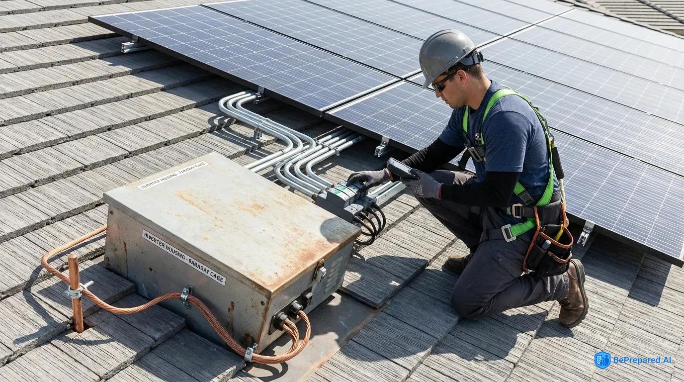
For solar array wiring, this typically means running cables in continuous metal conduit, properly bonded at every junction and grounded at both ends. The conduit itself becomes the shield. Alternatively, you can use armored cable with an integrated metal shield, though ensuring proper shield continuity at every connection point requires careful installation.
The critical principle is that the shield must form a continuous conductive path from the array to your equipment ground—any break in continuity creates a gap where EMP energy can couple into the inner conductors.
Enclosure shielding provides the final protection layer. Your inverter, charge controller, and other sensitive electronics should reside in a metal enclosure that forms a Faraday cage, with all penetrations (for cables, ventilation, access doors) properly treated to maintain shielding effectiveness. A simple metal box provides significant protection, but the details matter enormously.
The enclosure must have excellent electrical continuity—welded or tightly gasketed seams, not overlapping panels with gaps. Cable entries must use shielded connectors or EMI glands that maintain the enclosure's shielding integrity. Ventilation openings can't exceed specific sizes relative to the wavelengths you're protecting against; for E1 protection, this means small holes or honeycomb vents rather than large grilles.
The most practical approach for most installations involves using industrial electrical enclosures rated for EMI/RFI shielding. These enclosures come with properly designed door gaskets, shielded cable entries, and EMI-rated ventilation panels. While expensive compared to standard electrical boxes, they provide verified shielding effectiveness and eliminate the guesswork from enclosure design.
The enclosure ground connection must be bonded to your system ground through heavy conductors—at least 6 AWG copper, preferably larger—with the shortest possible path length.
System Integration and Protection Coordination
The individual protection elements—surge suppressors, shielded cables, and shielded enclosures—only provide effective protection when properly integrated into a coherent system. This requires careful attention to grounding architecture. The standard electrical practice of having separate grounds for different purposes (equipment ground, lightning ground, communications ground) creates multiple ground reference points that can develop significant voltage differences during an EMP event. These voltage differences drive destructive currents through any equipment connected between the different grounds.
EMP-hardened installations require a unified grounding system—a single-point ground where all protective devices, shields, and equipment grounds connect together. This ground point must have extremely low impedance to earth, achieved through multiple ground rods, ground grids, or other low-impedance grounding systems. The National Renewable Energy Laboratory recommends that ground system resistance should be below 5 ohms for effective EMP protection, with lower values providing better performance .
From this single-point ground, you establish your protection zones. The outermost zone includes your solar array—inherently exposed to the EMP environment. The transition point where array cables enter your building or equipment enclosure defines the boundary where you install your first-stage surge protection and where cable shields connect to ground. This creates a protected zone inside the shield where field strengths are reduced by the shielding effectiveness of your cables and enclosure.
Critical equipment like inverters and charge controllers reside in the innermost protection zone—inside the shielded equipment enclosure, protected by both the building/enclosure shield and the surge protectors at the cable entry points. This layered approach, called "defense in depth," ensures that even if one protection layer is partially defeated, subsequent layers provide backup protection.
Proper grounding techniques are essential to protection effectiveness. Studies demonstrate that proper grounding can reduce EMP-induced voltage by up to 85% , making it one of the most cost-effective protection measures you can implement. The difference between adequate grounding and excellent grounding often determines whether your system survives an EMP event intact or suffers catastrophic damage.
Implementation and Installation Guidelines
The theoretical protection design on paper transforms into actual resilience only through meticulous installation that respects the physics of electromagnetic coupling and the critical importance of every ground connection, shield termination, and component placement. An EMP-hardened solar installation isn't difficult to build, but it is unforgiving of shortcuts and casual workmanship.
The difference between a system that survives an EMP event and one that fails often comes down to details measured in inches—the length of a ground wire, the quality of a shield termination, the tightness of an enclosure gasket.
Equipment Placement and Enclosure Preparation
Begin installation by establishing your equipment location and preparing the shielded enclosure. The enclosure should be positioned to minimize the length of cable runs from your solar array while maintaining accessibility for maintenance. If you're installing in an existing building, an interior location provides inherent shielding from the building structure, though you'll still need a properly rated equipment enclosure. For standalone installations, the equipment enclosure itself becomes your primary shield.
Before mounting any equipment, verify the enclosure's shielding integrity. Inspect all seams for continuous contact—the door gasket should compress evenly around the entire perimeter when closed, with no visible gaps. Check that the gasket material is conductive (typically conductive elastomer or metal mesh embedded in rubber) rather than standard weatherstripping.
Test the electrical continuity between the door and enclosure body with a low-resistance ohmmeter; you should measure less than 0.01 ohms across the gasket. Higher resistance indicates poor contact that will degrade shielding effectiveness.
Cable entry points require careful preparation. Each penetration through the enclosure wall must maintain the shield integrity through proper EMI glands or shielded connectors. For installations with multiple cables, a shielded cable entry panel provides a clean solution—a metal panel with multiple gland positions that mounts to the enclosure wall, maintaining shielding through metal-to-metal contact and gaskets.
The alternative involves individual EMI cable glands for each penetration, each with proper bonding to the enclosure wall through toothed washers or bonding jumpers that penetrate any paint or coating to establish metal-to-metal contact.
Grounding System Installation
The grounding system forms the foundation of your EMP protection, and it must be installed first. Drive ground rods at least 8 feet deep in soil with reasonable conductivity, spacing multiple rods at least twice their length apart to avoid overlapping resistance zones. In rocky soil or areas with poor ground conductivity, you may need to install a ground grid—a network of buried copper conductors that provides low-impedance earth connection through increased surface area.
Connect the ground rods together with at minimum 2 AWG bare copper wire, using exothermic welds or listed compression connectors rated for direct burial. Bring this ground system to a central grounding busbar—a substantial copper or bronze bar with multiple connection points. This busbar becomes your single-point ground reference where all protective devices, shields, and equipment grounds will connect.
The connection between your ground rod system and the grounding busbar must be heavy—4 AWG minimum, 2 AWG or larger preferred—and as short as practical. Route this conductor in a straight line without loops or coils that would add inductance. Every foot of length and every bend adds impedance that degrades protection effectiveness.
Proper bonding techniques reduce shield resistance to less than 0.1 ohms, a critical threshold for effective EMP protection .
If your installation includes a grid connection, the relationship between your EMP protection ground and the utility ground requires careful consideration. Electrical code typically requires bonding these grounds together, but this creates a pathway for grid-coupled EMP energy to reach your equipment. The solution involves installing a high-speed disconnect between your system and the grid—either a manual disconnect that you can open when EMP threat levels are high, or an automatic system that senses abnormal grid conditions and isolates your installation.
This disconnect must be rated to interrupt DC current if it's on the solar side of your inverter, requiring special DC-rated contactors or breakers.
Solar Array Wiring and Protection Installation
Run conductors from your solar array to the equipment enclosure using continuous metal conduit or armored cable with integral metal shielding. The conduit must be electrically continuous—every coupling must have metal-to-metal contact, not just mechanical connection through plastic bushings or couplings. Use listed conduit fittings appropriate for EMI protection, or supplement standard fittings with bonding jumpers that ensure electrical continuity across each joint.
At the array end, bond the conduit to the array frame structure through heavy bonding jumpers—at least 6 AWG copper with proper lugs crimped or bolted to both the conduit and the frame. This connection must be weatherproof and corrosion-resistant; use stainless steel hardware and apply anti-oxidant compound to aluminum connections. The array frame itself connects to your grounding system through a dedicated equipment grounding conductor run alongside the power conductors.
Where the conduit enters your equipment enclosure, bond it to the enclosure wall through proper EMI glands or bonding hubs. These specialized fittings ensure 360-degree contact between the conduit and the enclosure, maintaining shield continuity. Inside the enclosure, install your first-stage surge protection immediately at the cable entry point—within 6 inches of where the conductors emerge from the conduit.
Mount the surge protector on a grounded metal surface or directly to the grounding busbar to minimize ground lead length.
The surge protector must be sized for your system voltage and current. For a typical 48-volt battery system with solar array voltage up to 100 volts, select protectors rated for at least 150 volts DC continuous operation with clamping voltage below 200 volts. The current rating must exceed your maximum array short-circuit current by a factor of at least 2. Install protectors on both positive and negative conductors relative to ground—EMP-induced voltages can appear on either polarity.
Properly shielded cables reduce induced voltages by a factor of 100, but only if the shield is grounded correctly . Connect the conduit shield to your grounding busbar through the shortest possible path, using conductors at least as large as the power conductors they're protecting. This creates a low-impedance path that diverts induced currents to ground before they can enter your equipment.
Equipment Installation and Interconnection
Mount your charge controller, inverter, and other electronics inside the shielded enclosure, maintaining at least 2 inches of clearance from the enclosure walls to avoid creating unintended ground loops or shield penetrations. Use insulated standoffs or mounting brackets that prevent direct metal-to-metal contact between equipment cases and the enclosure while still allowing proper equipment grounding through dedicated ground conductors.
Connect each piece of equipment to the grounding busbar through individual ground conductors—don't daisy-chain equipment grounds. Each ground conductor should be 6 AWG or larger, routed in the most direct path possible without loops or coils. Strip insulation back far enough to allow proper crimped or bolted connections at both ends. Use star washers or toothed washers to penetrate any anodizing or coating on equipment cases.
Interconnecting wiring between components inside the enclosure should use the shortest practical lengths, but avoid creating tight bundles of parallel conductors that increase mutual inductance. Route power and control wiring separately where possible, crossing at right angles when they must intersect. This reduces coupling between circuits and minimizes the loop areas where magnetic fields can induce currents.
For battery connections, install a second stage of surge protection between the charge controller output and the battery bank. Batteries themselves are relatively EMP-resistant, but the battery management system (if using lithium batteries) contains sensitive electronics requiring protection. The surge protector at this location sees lower voltage swings than the solar input protection, but it provides critical backup protection and catches any transients that coupled through the charge controller.
Continuous Shield Grounding and Bonding
The single most important installation detail for EMP protection is continuous shield grounding—ensuring that every shield, every metal enclosure, and every protective device ground connects to the single-point ground through low-impedance paths. Research from the Department of Homeland Security demonstrates that continuous shield grounding reduces EMP coupling by 40 dB or more compared to installations with discontinuous or high-impedance ground connections .
Walk through your installation with a low-resistance ohmmeter, measuring the resistance between every shielded component and the grounding busbar. You should measure less than 0.1 ohms for properly bonded connections. Higher resistance indicates problems—loose connections, corroded surfaces, or undersized conductors. These problems may not affect normal system operation, but they create vulnerabilities during EMP events when thousands of amperes of induced current must be safely diverted to ground.
Pay special attention to bonding across movable joints like enclosure doors or hinged panels. These require flexible bonding straps that maintain electrical continuity while allowing movement. Standard copper braid works, but specialized EMI bonding straps with multiple contact points provide better performance. Install bonding straps at multiple points across wide doors to ensure uniform contact around the entire perimeter.
Any penetrations through the shielded enclosure for ventilation, displays, or controls must maintain shielding effectiveness. Ventilation panels should use honeycomb or waveguide-below-cutoff designs that allow airflow while blocking electromagnetic energy. Display windows require conductive mesh or transparent conductive coatings. Control penetrations like switches or adjustment knobs need EMI-filtered feedthroughs.
These specialized components are expensive, but they're essential for maintaining the enclosure's shielding integrity.
Testing and Verification Protocols
An EMP-hardened solar installation represents a significant investment in equipment, specialized components, and installation labor. The only way to verify that this investment will actually protect your system is through rigorous testing and verification. Unlike normal electrical work where functionality testing is straightforward—does power flow when you flip the switch?—EMP protection requires testing that the protection elements function correctly, that shielding is effective, and that all the critical ground bonds and shield connections meet specifications.
Initial Installation Verification
Begin verification immediately after installation, before closing up enclosures or making the system operational. Use a low-resistance digital ohmmeter capable of measuring milliohms accurately. Test every ground connection from the component to the grounding busbar, documenting the resistance. Create a test log with the measured resistance for each connection point—this becomes your baseline for future maintenance inspections.
Ground connection resistance testing reveals poor crimps, corroded connections, or undersized conductors. Any measurement above 0.1 ohms requires investigation and correction. Don't accept marginal connections—the difference between 0.1 ohms and 0.5 ohms seems trivial, but during an EMP event when thousands of amperes flow through these connections, even small resistances create significant voltage drops that can damage equipment.
Shield continuity testing verifies that your conduit and cable shields form continuous conductive paths. Measure resistance between the array frame and the equipment enclosure—you should see less than 1 ohm for properly bonded shield connections. Test at multiple points along long conduit runs to verify that every coupling and junction maintains electrical continuity. A single poor connection in a 100-foot conduit run creates a gap in your shield where EMP energy can couple into the inner conductors.
Surge protector verification requires specialized equipment, but you can perform basic checks with standard test gear. Verify that the protector is properly connected between the protected conductors and ground—reversed or miswired surge protectors provide no protection. Check the indicator lights or status displays if your protectors include them. Some surge protectors include built-in test circuits that verify functionality; use these if available.
Shield Effectiveness Testing
The most rigorous verification involves measuring the actual shielding effectiveness of your enclosure and cable shields. This requires specialized RF test equipment—a signal generator, receiving antenna, and spectrum analyzer or field strength meter. Professional testing services can perform this measurement if you don't have access to the equipment. For high-value installations, professional verification provides valuable documentation and peace of mind.
Shield effectiveness testing must show at least 60 dB attenuation at frequencies from 10 kHz to 1 GHz to provide adequate EMP protection . This means that electromagnetic field strength inside the shielded enclosure should be 1/1000th of the field strength outside. Testing involves placing a transmitting antenna outside the enclosure while measuring field strength inside at various frequencies across the spectrum.
Perform testing with the enclosure closed and all cable shields connected as they will be in actual operation. Walk around the enclosure with the receiving antenna, looking for hot spots where shielding is less effective—these indicate shield penetrations, poor door gasket contact, or other shielding defects. Pay particular attention to cable entry points, ventilation panels, and door seams.
If testing reveals shielding deficiencies, systematically investigate potential causes. Poor door gasket contact is a common issue—verify that the gasket compresses evenly around the entire perimeter and that the door latches provide sufficient pressure. Cable entry points may need additional EMI glands or better bonding to the enclosure. Ventilation panels must use proper EMI-rated designs, not standard grilles or louvers.
Functional Testing Under Simulated Conditions
While you can't safely subject your installation to an actual EMP, you can perform functional testing that verifies protection system operation under surge conditions. This requires a surge generator capable of producing test pulses that simulate lightning and switching transients. Professional-grade surge generators are expensive, but electrical testing services can perform this testing as part of commissioning.
Surge testing involves injecting calibrated test pulses into your system while monitoring for proper surge protector operation and verifying that no damage occurs to protected equipment. Start with low-level test pulses well within your protectors' ratings, then progressively increase to verify performance at rated levels. The surge protectors should clamp the voltage to safe levels, with no voltage spikes reaching sensitive equipment.
Document the test results, including the test pulse amplitude, rise time, and the measured voltage at various points in your system. This creates a baseline for future testing and verification. Surge protectors degrade over time and with each surge event they suppress, so periodic retesting verifies that protection remains effective.
Maintenance and Inspection Schedules
EMP protection isn't a one-time installation—it requires ongoing maintenance to ensure long-term effectiveness. Studies demonstrate that annual maintenance extends protection effectiveness by 5-7 years compared to unmonitored installations . Create a maintenance schedule that includes both visual inspections and electrical testing.
Quarterly visual inspections should examine all accessible ground connections, shield bonds, and enclosure gaskets. Look for corrosion, loose connections, or physical damage. Verify that enclosure doors close properly and that gaskets show no signs of deterioration. Check surge protector status indicators if present, and verify that no unauthorized modifications or additions have compromised the protection system.
Annual electrical testing should repeat the initial verification measurements. Test ground connection resistance at all major bonding points, comparing results to your baseline measurements. Significant increases in resistance indicate developing problems—corrosion, loosening connections, or conductor damage. Shield continuity testing verifies that all shield bonds remain intact and effective.
Every three to five years, consider professional shield effectiveness testing to verify that enclosure shielding remains within specifications. Gaskets degrade over time, ventilation panels can corrode, and enclosure modifications or additions may have compromised shielding. Professional testing provides objective verification that your protection system maintains its design effectiveness.
Surge protectors should be inspected regularly and replaced when they show signs of degradation. Many modern surge protectors include end-of-life indicators that signal when the protection elements have degraded below acceptable levels. Don't ignore these indicators—establish a proactive inspection schedule and replace components showing wear or damage before they fail.
Ready to ensure your installation meets professional standards? Download our Complete EMP Protection Installation Checklist for a comprehensive verification guide that covers every critical measurement, test point, and inspection requirement. This detailed checklist walks you through the complete testing and verification process, ensuring your EMP-hardened solar system will perform when you need it most.
Document every inspection, test, and maintenance activity in a system logbook. Record measured values, any anomalies discovered, and corrective actions taken. This documentation provides a history of your system's protection status and helps identify developing trends that might indicate emerging problems. If you ever need to file an insurance claim or demonstrate due diligence in system protection, this documentation becomes invaluable evidence of proper installation and maintenance.
The investment in testing and verification represents a small fraction of your total system cost, but it's the only way to confirm that your EMP protection will actually function when needed. A system that looks properly installed but has never been tested is a gamble. Rigorous testing transforms hope into confidence, providing objective evidence that your solar installation can survive the electromagnetic threats that would destroy unprotected systems.
In a post-EMP scenario where functioning power systems become priceless, that confidence—backed by documented test results—represents the true value of proper installation verification. Your EMP-hardened solar system isn't just an insurance policy against electromagnetic threats; it's a carefully engineered solution built on sound physics, proper component selection, meticulous installation, and verified performance. When the grid goes dark and unprotected systems fail, your investment in comprehensive EMP protection will prove its worth many times over.